Basic lab topology with EIGRP

In today’s lab we will setup a basic topology in GNS3 using EIGRP, NAT, VLANs and access list to allow subnets. In the future we will add features such as DHCP, DNS and some other functions.
Basic lab topology setup will use a NAT cloud as the internet gateway, Cisco CSR1000v as the router, a Cisco IOSvL2 215.2-1 as the core switch, and a Cisco IOSvL2 215.2-2 as the access switch.
- Hostnames
- IP and Subnets
- Trunk and Access ports
- NAT
- EIGRP
1. Hostnames
For the first step, we will set up the hostnames for the router and switches.
Cisco CSR1000v – Router Internet Gateway – name R1
en
conf t
host R1
end
CiscoIOSvL2215.2 – 1 – Core Switch, configure all subnets, L3 networking – name CORE-SW
en
conf t
host CORE-SW
end
CiscoIOSvL215.2 – 2 – Access Switch, switch to connect users – name SW-A
en
conf t
host SW-A
end
2. IP and Subnets
For the second step, we will configure VLANs and IP addresses on the VLAN interfaces and loopback interfaces.
Configure VLANs on CORE-SW (L3 Routing)
# CORE-SW
en
conf t
vlan 10
vlan 20
int vlan 1
ip address 10.1.100.1 255.255.255.0
no shut
int vlan 10
ip address 10.1.10.1 255.255.255.0
no shut
int vlan 20
ip address 10.1.20.1 255.255.255.0
no shut
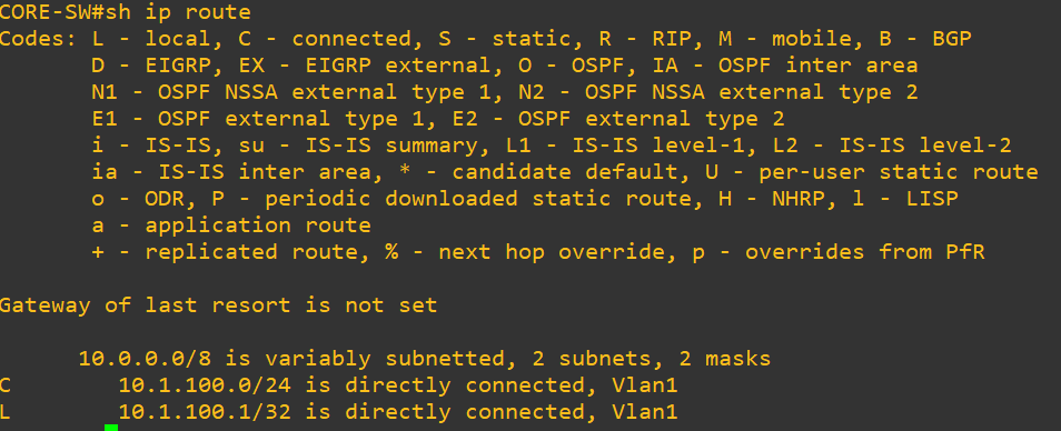
endTesting
sh ip routeResult looks like this:
Display VLANs brief
sh vlan brief
sh ip int brief
Testing ping to vlan 1
ping 10.1.100.1Configure VLANs on SW-A
# SW-A
en
vlan 10
vlan 20
int vlan 1
ip address 10.1.100.2 255.255.255.0
no shut
int vlan 10
ip address 10.1.10.2 255.255.255.0
no shut
int vlan 20
ip address 10.1.20.2 255.255.255.0
no shut
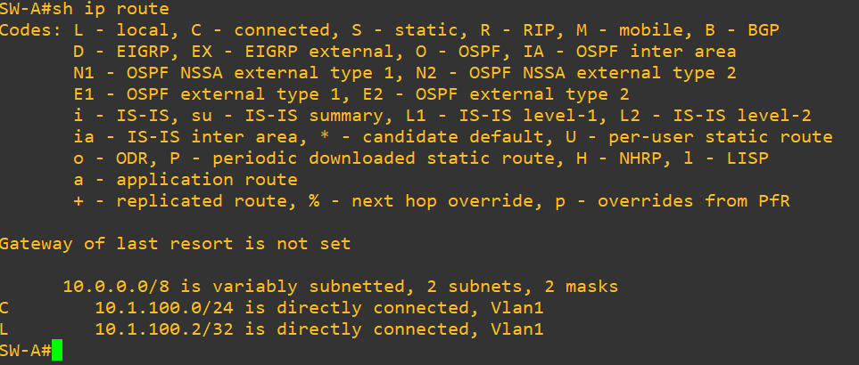
endTesting
sh ip routeResult looks like this
Testing ping
ping 10.1.100.1
ping 10.1.10.2
Result looks like this

Configuring loopback interface on Router R1
en
conf t
int loopback 0
ip address 1.1.1.1 255.255.255.255
no shut
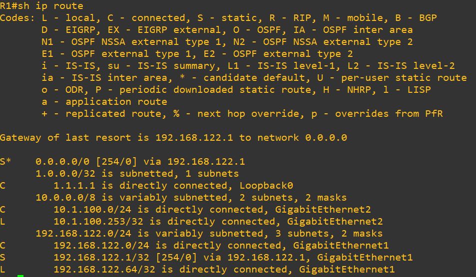
endConfiguring vlan 1 interface on Router (GigabitEthernet2)
en
conf t
int gigabitEthernet 2
ip address 10.1.100.253 255.255.255.0
no shut
end
sh ip int brief
Configuring loopback interface on CORE-SW
en
conf t
int loopback 0
ip address 2.2.2.2 255.255.255.255
no shut
end
3. Trunk and Access ports
In the next step, we will configure the trunk and access ports.
CORESW – ports configuration
# Access port on interface G0/0
en
conf t
int g0/0
switchport mode access
switchport nonegotiate
no shut
end
# Trunk port on interface G1/0
conf t
int g1/0
switchport trunk encapsulation dot1q
switchport mode trunk
switchport nonegotiate
no shut
end
SW-A – ports configuration
# Trunk port on interface G0/0
en
conf t
int g0/0
switchport trunk encapsulation dot1q
switchport mode trunk
no shut
end
# Access port on interface G1/0
en
conf t
int g1/0
switchport mode access
switchport access vlan 10
no shut
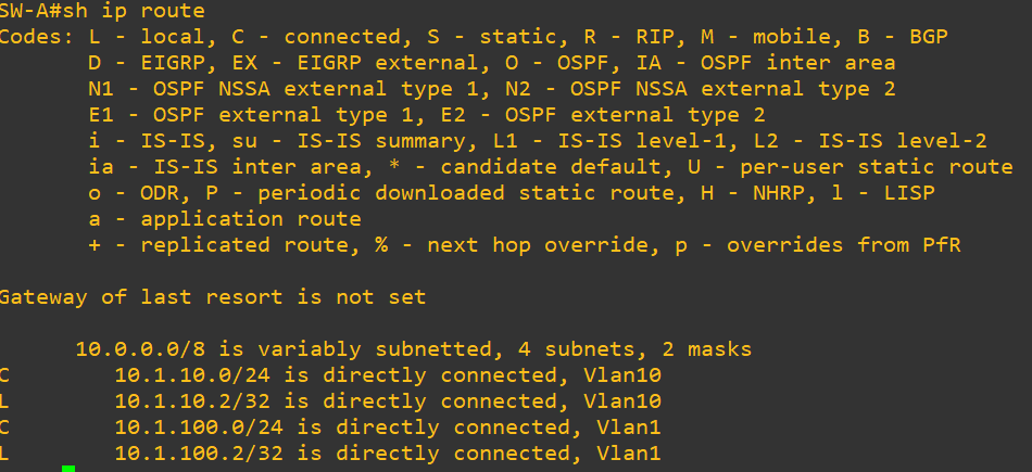
endTesting
sh ip routeResults looks like this
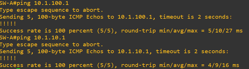
Ping
ping 10.1.100.1
ping 10.1.10.1
Result looks like this
Pings from CORE-SW
ping 10.1.100.2
ping 10.1.10.2
Results looks like this

Routing table on CORE-SW
sh ip routeResults looks like this

4. NAT
Configuring NAT for IP address conservation on Router (Cisco CSR1000v)
# R1
en
conf t
int G1
ip nat outside
shut
no shut
int G2
ip nat inside
shut
no shut
end
Add an access list for NAT
en
conf t
ip nat inside source list 1 interface gigabitEthernet 1 overload
Add access list 1 to permit 10.0.0.0 subnet
access-list 1 permit 10.0.0.0 0.255.255.2555. EIGRP Routing
Configuring EIGRP on Router R1
en
conf t
router eigrp 100
no auto-summary
network 10.1.100.253 0.0.0.0
network 1.1.1.1 0.0.0.0
redistribute static metric 10000 100 255 1 1500
end
wr!
Display routes
Result looks like this
Configuring EIGRP on CORE-SW
en
conf t
router eigrp 100
network 10.0.0.0
network 2.2.2.2 0.0.0.0
no auto-summary
end
wr!
Configure static route on SW-A
en
conf t
ip route 0.0.0.0 0.0.0.0 10.1.100.1
end
wr!
Configure ip on PC-1
ip 10.1.10.3 10.1.10.2Test ping to google (8.8.8.8)
ping 8.8.8.8That’s all for today’s Basic topology using EIGRP in GNS3. If you have ideas on how to improve this topology or what information should I add, leave a comment below
Thanks. I hope it will help you to progress your skills.